|
KLIPPEL ANALYZER SYSTEM Large Signal Identification (LSI) Including Thermal Data |
|
|

|
Driver
Name: |
SS 9 |
|
Driver
Comment: |
|
|
Measurement: |
LSI
Woofer Driver (Thermal) |
|
Measurement
Comment: |
|
|
Date: |
07/21/07 |
|
Time: |
19:39:03 |
Comments
Obvious shorting method
BL and KMS symmetry is
almost perfect
Note XBl
and XC are calculated using the subwoofer distortion targets of 10% as this
driver is to be used as a midbass (Using 10% values),
the XBl is 13.4mm and the XC is 10.6mm
Overview
This Report illustrates the powerful features of the Large Signal Identification Module (LSI):
< nonlinear speaker parameters versus displacement and current
< coefficients of the power series expansion of the nonlinear parameters
< derived speaker parameters such as resonance frequency and loss factors
< parameters at the rest position (parameters for linear modelling)
< parameter variation versus time
< state variables of the speaker (temperature, displacement, )
< contribution of each nonlinearity to the total distortion (distortion analysis)
< suggestions for loudspeaker improvements (remedy parameters)
Nonlinear Characteristics
The dominant nonlinearities are modelled by variable parameters such as
|
Bl(x) |
instantaneous electro-dynamic coupling factor
(force factor of the motor) defined by the integral of the magnetic flux
density B over voice coil length l as a function of displacement |
|
KMS(x) |
mechanical stiffness of driver suspension a
function of displacement |
|
LE(i) |
voice coil inductance as a function of input
current (describes nonlinear permeability of the iron path) |
|
LE(x) |
voice coil inductance as a function of
displacement |
More information
about optimising these parameters can be found in the article Displacement
limits
.png)
The electrodynamic coupling factor, also called Bl-product or force factor Bl(x), is defined by the integral of the magnetic flux density B over voice coil length l, and translates current into force.
In traditional modeling this parameter is assumed to be constant. The force factor Bl(0) at the rest position corresponds with the Bl-product used in linear modeling.
The red curve displays Bl over the entire displacement range covered during the measurement. You see the typical decay of Bl when the voice coil moves out of the gap.
At the end of the measurement, the black curve shows the confidential range (interval where the voice coil displacement in this range occurred 99% of the measurement time). During the measurement, the black curve shows the current working range.
The dashed curve displays Bl(x) mirrored at the rest position of the voice coil this way, asymmetries can be quickly identified.
Since a laser was connected during the measurement, a "coil in / coil out" marker is displayed on the bottom left / bottom right.
More information regarding Bl(x) and its optimization can be found in the article Optimal Voice Coil Rest Position
.png)
The stiffness KMS(x) describes the
mechanical properties of the suspension. It's inverse is the compliance CMS(x)
More information regarding Kms(x) and its optimization can be found in the article Adjusting Mechanical Suspension
.png)
.png)
The inductance components Le (x) and Bl(i) of most drivers have a strong asymmetric characteristic. If the voice coil moves towards the back plate the inductance usually increases since the magnetic field generated by the current in the voice coil has a lower magnetic resistance due to the shorter air path.
The nonlinear inductance Le(x) has two nonlinear effects. First the variation of the electrical impedance with voice coil displacement x affects the input current of the driver. Here the nonlinear source of distortion is the multiplication of displacement and current. The second effect is the generation of a reluctance force which may be interpreted as an electromagnetic motor force proportional to the squared input current.
The flux modulation Bl(i) has two effects too. On the
electrical side the back EMF Bl(i)*v
produces nonlinear distortion due to the multiplication of current i and velocity v. On the mechanical side the driving force
F = Bl(i)*i comprises a nonlinear term due to the squared current i. This force produces similar effects as the variable term
Le(x) in the
Nonlinear and thermal Parameters
The displacement limits XBL,
XC, XL and Xd
describe the limiting effect for the
force factor Bl(x), compliance Cms(x), inductance Le(x) and Doppler
effect, respectively, according to the threshold values Blmin,
Cmin, Zmax
and d2 used. The thresholds Blmin=
82 %, Cmin=75 %, Zmax=10 % and d2=10% generate for a
two-tone-signal (f1=fs, f2=8.5fs)
10 % total harmonic distortion and 10 % intermodulation
distortion. The thresholds Blmin= 70 %, Cmin=50 %, Zmax=17
% create 20 % total harmonic distortion which is becoming the standard for
acceptable subwoofer distortion thresholds.
These parameters are defined
in more detail in the papers: AN04 Measurement of
Peak Displacement Xmax, AN05
- Displacement Limits due to Driver Nonlinearities. , AN17
- Credibility of Nonlinear Parameters, Prediction
of Speaker Performance at High Amplitudes, Assessment
of Voice Coil Peak Displacement Xmax, and Assessing
Large Signal Performance of Loudspeakers
The thermal parameters describe the resistance and capacity of the coil and magnet and the velocity depending convection cooling.
This new model for thermal behavior of a speaker is detailed in the paper: Nonlinear Modeling of Heat Transfer.
|
|
|||
|
Symbol |
Number |
Unit |
Comment |
|
Displacement Limits |
|
|
thresholds can be changed in Processing property page |
|
X Bl @ Bl min=70% |
13.5 |
mm |
Displacement limit due to force factor variation |
|
X C @ C min=50% |
>14.5 |
mm |
Displacement limit due to compliance variation |
|
X L @ Z max=10 % |
5.0 |
mm |
Displacement limit due to inductance variation |
|
X d @ d2=10% |
48.0 |
mm |
Displacement limit due to IM distortion (Doppler) |
|
|
|||
|
alpha |
0.259304 |
|
Heating of voice coil by eddy currents |
|
alphaOrg |
|
|
Heating of voice coil by eddy currents (without limits) |
|
Rtv |
1.207180 |
K/W |
thermal resistance coil ==> pole tips |
|
rv |
0.666803 |
Ws/Km |
air convection cooling depending on velocity |
|
Rtm |
0.550532 |
K/W |
thermal resistance magnet ==> environment |
|
tau m |
40 |
min |
thermal time constamt of magnet |
|
Ctm |
4385.657715 |
Ws/K |
thermal capacity of the magnet |
|
tau v |
115.219452 |
s |
thermal time constant of voice coil |
|
Ctv |
95.445122 |
Ws/K |
thermal capacity of the voice coil |
|
|
|||
|
delta Tw |
95 |
K |
Temperature increase in Warm Resistance Mode |
|
delta Tc |
94 |
K |
Temperature increase in Convection Mode |
|
delta Te |
38 |
K |
Temperature increase in Eddy Mode |
|
Pcoil(warm) |
83.189354 |
W |
Pcoil in warm mode |
|
Pcoil(conv) |
109.966309 |
W |
Pcoil in convection mode |
|
Ptv(mag.beg) |
48.910084 |
W |
power heating the coil at beginning of magnet mode |
|
Ptv(mag.mid) |
49.003696 |
W |
power heating the coil sampled in the middle of magnet mode |
|
Ptv(mag.end) |
48.442669 |
W |
power heating the coil at end of magnet mode |
|
Ptm(mag.beg) |
99.213829 |
W |
power heating the magnet at beginning of magnet mode |
|
Ptm(mag.mid) |
98.905685 |
W |
power heating the magnet sampled in the middle of magnet mode |
|
Ptm(mag.end) |
97.308136 |
W |
power heating the magnet at end of magnet mode |
|
|
|||
|
f1 |
-0.004977 |
1/A |
coefficient (1) of Inductance over current (flux modulation) |
|
f2 |
-0.000121 |
1/A^2 |
coefficient (2) of Inductance over current (flux modulation) |
|
|
|||
|
Bl0 = Bl (X=0) |
26.330 |
N/A |
constant part in force factor |
|
Bl1 |
0.11557 |
N/Amm |
1st order coefficient in force factor expansion |
|
Bl2 |
-0.035345 |
N/Amm^2 |
2nd order coefficient in force factor expansion |
|
Bl3 |
-8.5741e-006 |
N/Amm^3 |
3rd order coefficient in force factor expansion |
|
Bl4 |
3.2780e-006 |
N/Amm^4 |
4th order coefficient in force factor expansion |
|
Bl5 |
|
N/Amm^5 |
5th order coefficient in force factor expansion |
|
Bl6 |
|
N/Amm^6 |
6th order coefficient in force factor expansion |
|
Bl7 |
|
N/Amm^7 |
7th order coefficient in force factor expansion |
|
Bl8 |
|
N/Amm^8 |
8th order coefficient in force factor expansion |
|
|
|||
|
L0 = Le (X=0) |
4.0482 |
mH |
constant part in inductance |
|
L1 |
-0.088895 |
mH/mm |
1st order coefficient in inductance expansion |
|
L2 |
0.0024967 |
mH/mm^2 |
2nd order coefficient in inductance expansion |
|
L3 |
8.0338e-005 |
mH/mm^3 |
3rd order coefficient in inductance expansion |
|
L4 |
-1.3017e-006 |
mH/mm^4 |
4th order coefficient in inductance expansion |
|
L5 |
|
mH/mm^5 |
5th order coefficient in inductance expansion |
|
L6 |
|
mH/mm^6 |
6th order coefficient in inductance expansion |
|
L7 |
|
mH/mm^7 |
7th order coefficient in inductance expansion |
|
L8 |
|
mH/mm^8 |
8th order coefficient in inductance expansion |
|
|
|||
|
C0 = Cms (X=0) |
0.26399 |
mm/N |
constant part in compliance |
|
C1 |
0.0051193 |
1/N |
1st order coefficient in compliance expansion |
|
C2 |
-0.00042359 |
1/Nmm |
2nd order coefficient in compliance expansion |
|
C3 |
-5.3496e-006 |
1/Nmm^2 |
3rd order coefficient in compliance expansion |
|
C4 |
4.0003e-007 |
1/Nmm^3 |
4th order coefficient in compliance expansion |
|
C5 |
|
1/Nmm^4 |
5th order coefficient in compliance expansion |
|
C6 |
|
1/Nmm^5 |
6th order coefficient in compliance expansion |
|
C7 |
|
1/Nmm^6 |
7th order coefficient in compliance expansion |
|
C8 |
|
1/Nmm^7 |
8th order coefficient in compliance expansion |
|
|
|||
|
K0 = Kms (X=0) |
|
N/mm |
constant part in stiffness |
|
K1 |
-0.081636 |
N/mm^2 |
1st order coefficient in stiffness expansion |
|
|
0.0090830 |
N/mm^3 |
2nd order coefficient in stiffness expansion |
|
K3 |
-0.00014982 |
N/mm^4 |
3rd order coefficient in stiffness expansion |
|
K4 |
-2.9248e-007 |
N/mm^5 |
4th order coefficient in stiffness expansion |
|
|
|||
Derived Loudspeaker
Parameters
For
the analysis and synthesis of loudspeaker system it is convenient to use special
transducer parameters:
|
fs (x) |
instantaneous
resonance frequency of the transducer varying with voice coil displacement |
|
QMS(x)
|
mechanical
loss factor of the transducer at fs
considering driver non-electrical resistances only |
|
QES(TV,
x) |
electrical
loss factor by considering the electrical resistance RE(TV)
only, |
|
QT(TV,
x) |
total
loss factor at fs and voice coil
temperature TV considering mechanical and electrical resistances RMS
and RE(TV) only. |
In
contrast to linear modelling most of these parameters are not constant but
depend on the instantaneous state of the transducer (displacement x, the voice
coil temperature TV).
.png)
.png)
.png)
.png)
Parameters at the Rest Position
The
value of the nonlinear parameters at the rest position (x=0) may be used
as input for the traditional linear modelling and may be referred as linear parameters.
Please note that these parameters depend on the instantaneous state of the
driver (voice coil temperature, peak value of displacement) and are presented
for three different modes of operation:
Mode |
Properties |
|
LARGE+WARM
|
the transducer is operated in the large signal domain, the peak value of the displacement is high (|x| < xmax), the variation of the parameters is not negligible, the voice coil temperature is increased (D TV > 0) due to heating. |
|
LARGE+COLD |
the transducer is operated in the large signal domain, the peak value of the displacement is high (|x| < xmax), the variation of the parameters is not negligible, the effect of heating is compensated while considering the cold voice coil resistance Re(D TV =0). |
|
SMALL
SIGNAL |
the transducer is operated in the small signal domain, the amplitude of the excitation signal is sufficiently small, the displacement is small in comparison to the allowed maximal displacement (|x| << xmax ), the variations of the nonlinear parameters are negligible, the increase of voice coil temperature is negligible (D TV » 0), the effects of the nonlinear, thermal and time-varying mechanisms are negligible, the transducer behaves almost linear. |
|
|
|||||
|
Symbol |
Large + Warm |
Large + Cold |
Small Signal |
Unit |
Comment |
|
Note: |
|
|
|
|
for accurate small signal parameters, use LPM module |
|
Delta Tv = Tv-Ta |
140 |
0 |
0 |
K |
increase of voice coil temperature during the measurement |
|
Xprot |
22.2 |
22.2 |
3.1 |
mm |
maximal voice coil excursion (limited by protection system) |
|
|
|||||
|
Re (Tv) |
9.34 |
6.10 |
6.10 |
Ohm |
(imported) voice coil resistance considering increase of voice coil temperature Tv |
|
Le (X=0) |
0.44 |
0.44 |
0.31 |
mH |
voice coil inductance at the rest position of the voice coil |
|
L2 (X=0) |
2.93 |
2.93 |
1.26 |
mH |
para-inductance at the rest position due to the effect of eddy current |
|
R2 (X=0) |
0.94 |
0.94 |
0.94 |
Ohm |
resistance at the rest position due to eddy currents |
|
Cmes (X=0) |
1738 |
1738 |
1147 |
µF |
electrical capacitance representing moving mass |
|
Lces (X=0) |
46.37 |
46.37 |
33.71 |
mH |
electrical inductance at the rest position representing driver compliance |
|
Res (X=0) |
35.88 |
35.88 |
50.27 |
Ohm |
resistance at the rest position due to mechanical losses |
|
|
|||||
|
Qms (X=0, Tv) |
6.95 |
6.95 |
9.27 |
|
mechanical Q-factor considering Rms only |
|
Qes (Tv) |
1.04 |
0.68 |
0.98 |
|
electrical Q-factor considering Re (Tv) only |
|
Qts (X=0, Tv) |
0.90 |
0.62 |
0.89 |
|
total Q-factor considering Re (Tv) and Rms only |
|
fs |
17.7 |
17.7 |
25.6 |
Hz |
driver resonance frequency |
|
|
|||||
|
Mms |
107.290 |
107.290 |
107.290 |
g |
(imported) mechanical mass of driver diaphragm assembly including voice-coil and air load |
|
Rms (X=0) |
1.720 |
1.720 |
1.860 |
kg/s |
mechanical resistance of total-driver losses |
|
Cms (X=0) |
0.75 |
0.75 |
0.36 |
mm/N |
mechanical compliance of driver suspension at the rest position |
|
Bl (X=0) |
10.37 |
10.37 |
10.37 |
N/A |
(imported) force factor at the rest position (Bl product) |
|
Vas |
57.0122 |
57.0122 |
27.3643 |
l |
equivalent air volume of suspension |
|
N0 |
0.029 |
0.045 |
0.045 |
% |
reference efficiency (2Pi-sr radiation using Re) |
|
Lm |
76.8 |
78.7 |
78.7 |
dB |
characteristic sound pressure level |
|
|
|||||
|
Sd |
232.00 |
232.00 |
232.00 |
cm² |
diaphragm area |
Transducer State
The state information
describes the progress of system identification and important transducer
variables in the last update interval of the measurement.
|
|
|||
|
Symbol |
Value |
Unit |
Comment |
|
Date |
2007-07-21 |
|
|
|
Time |
14:38:46 |
|
|
|
Serial number |
165 |
|
|
|
Mode |
Therm: Magnet 6g(7) |
|
|
|
Record |
1963/1963 |
|
|
|
Laser |
signal reliable |
|
|
|
t |
02:28:40 |
h:min:s |
measurement time |
|
Time remaining |
00:00:00 |
h:min:s |
recalculated at thermal mode(a) |
|
|
|||
|
Ei (t) |
27.6 |
% |
error current measurement |
|
Ex (t) |
10.4 |
% |
error laser measurement |
|
Eu (t) |
100.0 |
% |
error amplifier check |
|
|
|||
|
Delta Tv (Delta Tlim) |
139.9 (180.0) |
K |
increase of voice coil temperature (limit) |
|
Blmin (Bllim) |
39.2 (35.0) |
% |
minimal force factor ratio (limit) |
|
Cmin (Clim) |
25.0 (25.0) |
% |
minimal compliance ratio (limit) |
|
P (Plim) |
45.7965 (125.00) |
W |
real electrical input power (limit) |
|
Lmin |
99.9 |
% |
minimal inductance ratio |
|
Pn |
90.971040 |
W |
nominal electrical input power |
|
P Re |
34.146384 |
W |
Power heating voice coil |
|
Irms |
1.912 |
A |
rms value of the electrical input current |
|
Urms |
26.977 |
V |
rms value of the electrical voltage at the transducer terminals |
|
Ipeak |
5.542 |
A |
peak value of the electrical input current |
|
Upeak |
79.121 |
V |
peak value of the electrical voltage at the transducer terminals |
|
PC |
3.70 |
dB |
thermal power compression factor |
|
Glarge (Gmax) |
16.5 (26.0) |
dB |
gain of the excitation amplitude increased in the large signal domain (maximum) |
|
|
|||
|
Mech. system |
|
abs. |
import used to identify mechanical system in absolute quantities |
|
|
|||
|
Xdc |
-0.0 |
mm |
dc component of voice coil excursion measured in the last update intervall |
|
Xpeak |
0.7 |
mm |
positive peak value of voice coil excursion measured in the last update intervall |
|
Xbottom |
-0.7 |
mm |
negative peak value (bottom) of voice coil excursion measured in the last update intervall |
|
Xp+ |
16.3 |
mm |
upper limit of displacement range (99% probability) |
|
Xp- |
-16.5 |
mm |
lower limit of displacement range (99% probability) |
|
Xprot |
22.2 |
mm |
maximal voice coil excursion allowed by protection system |
|
v rms |
0.011 |
m/s |
voice coil velocity |
|
|
|||
|
Db |
0.1 |
% |
distortion factors representing contribution of nonlinear force factor |
|
Dl |
0.5 |
% |
distortion factor representing contribution of nonlinear inductance |
|
Dc |
0.0 |
% |
distortion factor representing contribution of nonlinear compliance |
|
|
|||
|
R th total |
4.10 |
K/W |
Delta Tv / P Re |
Voice
Coil Temperature D TV(t) and Power P(t)
The increase of the voice
coil temperature D TV(t) in comparison to the electric
input power P(t) versus measurement time t shows the thermal characteristic of
the transducer.
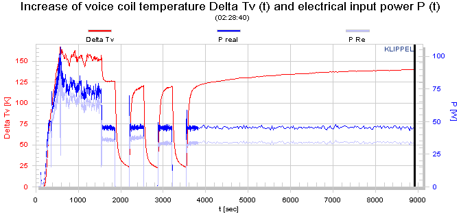
The different modes of operation can easily be identified in these time plots.
In the Amplifier Mode 1(7)
the loudspeaker is disconnected and the gain, polarity and distortion of the
power amplifier is checked. Here the amplitude of the current is zero.
In the Resistance Mode 2(7)
the dc-resistance of the voice coil is measured by a pulsed noise signal.
In the Linear Mode 3(7) the
loudspeaker is connected and noise at low amplitude is used as stimulus. The
transducer is operated in the small-signal domain. The temperature of the voice
coil at the end of this phase is used as reference temperature TA
which equals the ambient temperature.
In the Fast Mode 4(7) the
amplitude of the stimulus is increased and the limits of the allowed working
range are detected automatically. The
voice coil temperature TV increases with the input power. Both state
signals are used as protection variables and are compared with the limit values
Plim and Tlim
defined by the user.
In the Nonlinear Mode 5(7)
the learning speed is reduced and the nonlinear curves are measured at highest
precision.
The Thermal Mode 6(7)
consist of special heating and cooling phases to identify the thermal
parameters
Displacement x(t)
The displacement signal
versus measurement time is represented as
|
xpeak(t) |
positive peak of the voice coil displacement
in the update interval, |
|
xdc(t) |
averaged dc-value in
voice coil excursion, |
|
xbottom(t) |
negative peak value
(bottom value) of the voice coil displacement in the updated interval, |
|
xdcmax(t) |
maximal dc-value
in voice coil excursion
xdcmax(t)=(xpeak(t)+xbottom(t))/2 |
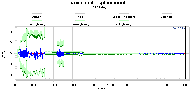
Asymmetrical nonlinearities
produce not only second- and higher-order distortions but also a dc-part in the
displacement by rectifying low frequency components.
For an asymmetric stiffness
characteristic the dc-components moves the voice coil for any excitation signal
in the direction of the stiffness minimum.
For an asymmetric force
factor characteristic the dc-component depends on the frequency of the
excitation signal. A sinusoidal tone below resonance (f<fS)
would generate or force moving the voice coil always in the force factor
maximum. This effect is most welcome for stabilizing voice coil position. However,
above the resonance frequency (f>fS)
would generate a dc-component moving the voice coil in the force factor minimum
and may cause severe stability problems.
For an asymmetric
inductance characteristic the dc-component moves the voice coil for any excitation
signal in the direction of the inductance maximum.
Please note that the
dynamically generated DC-components cause interactions between the driver
nonlinearities. A optimal rest position of the coil in the gap may be destroyed
by an asymmetric compliance or inductance characteristic at higher amplitudes.
The module "Large Signal Simulation (SIM)" allows systematic
investigation of the complicated behavior.
Distortion
Analysis
The Distortion Analysis
shows the contribution of each nonlinearity to the
total distortion in the reproduced output signal for the audio-like excitation
signal used during parameter measurement. The identified digital model of the
transducer makes it possible to measure the peak value of the distortion components generated by force
factor, compliance and inductance and to relate each value to the peak value of
the total output signal (sound pressure):
|
db |
relative degree of
distortion generated by nonlinear force factor Bl(x)
|
|
dL |
relative degree of distortion
generated by nonlinear inductance Le(x) |
|
dC |
relative degree of
distortion generated by nonlinear compliance Cms(x) |
|
dl(i) |
relative degree of
distortion generated by nonlinear inductance Le(i) permeability nonlinearity (flux modulation) |
The
distortion analysis is performed simultaneously with the parameter
identification. The relative degrees of distortion are expressed in percent
and presented versus measurement time (in
seconds) for the transducer under test:
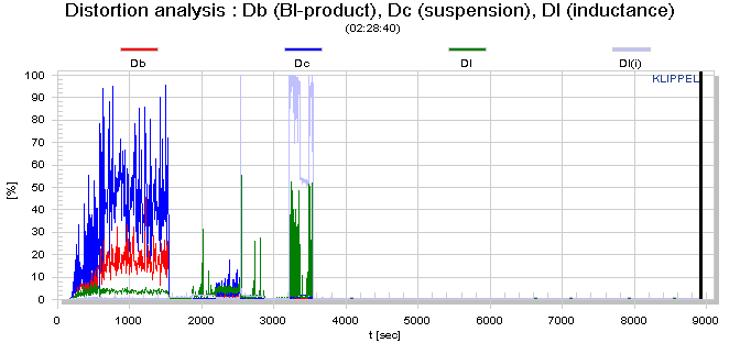
Each degree is a one-number representation of the distortion summarizing all of the harmonic and intermodulation components. Please note that the amount of distortion depend on the spectral properties of the excitation signal.
Remedies for Transducer Nonlinearities
You can find a detailed description of these non-linearities and their remedies in the papers Loudspeaker Nonlinearities - Causes and
Symptoms, Assessing
Large Signal Performance of Loudspeakers,
and Diagnosis
and Remedy of Nonlinearities
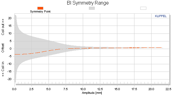
Bl Symmetry xb(x)
This curve
shows the symmetry point in the nonlinear Bl-curve
where a negative and positive displacement x=xpeak
will produce the same force factor
Bl(xb(x) + x) = Bl(xb(x) x).
If the
shift xb(x) is independent on the displacement
amplitude x then the force factor asymmetry is caused by an offset of the voice
coil position and can be simply compensated.
If the
optimal shift xb(x) varies with the
displacement amplitude x then the force factor asymmetry is caused by an asymmetrical
geometry of the magnetic field and can not completely be compensated by coil
shifting.
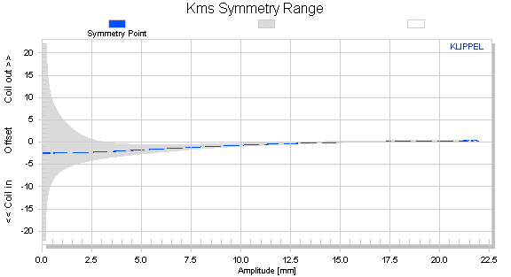
Kms Symmetry xc(x)
This curve shows the symmetry point in the nonlinear compliance
curve where a negative and positive displacement x=xpeak
will produce the same compliance value
kms(xc(x)
+ x) = kms(xc(x)
x).
A high value of the
symmetry point xc(x) at
small displacement amplitudes x » 0
indicates that the rest position does not agree with the minimum of the
stiffness characteristic. This may be caused by an asymmetry in the geometry of
the spider (cup form) or surround (half wave).
A high value of the symmetry point xc(x)
at maximal displacement x» xmax may be caused by asymmetric limiting of the
surround.